Thursday 8 November 2012

User stories, use cases or requirements?

A case of trust, responsibility and collaboration?

What is the exact difference between user stories, use cases or requirements? They all have the same goal: capture the needs of the business so they can be translated into a working software application. But there are differences in achieving the same goal.

Requirements tend to be very formal, text-driven and structured (using categories, sub requirements f.i.). They have to be unambiguous, 100% correct and complete. They also should be measurable and testable in the way that you should be able to verify how far the delivered software fulfills the requirements.

Use cases are also formal, text-driven, structured, complete and 100% correct. Use case diagrams deliver additional information on the roles that interact with the use cases and the system boundaries. Use cases are user oriented. They describe the interaction of the user and the system.

User stories however focus on the value they have for the user. They are less formal and are intended on stimulating open conversations: 


As a <user/role> I want <something> so that <benefit,value>

Conversations

Conversations should be conducted between all participants in the project, not only between business and product owner/analyst as in traditional projects. Also allow them to continue during the whole life cycle of the project. Completeness is not that important from the beginning: you do not need to specify all details upfront. You do what needs to be done at the right moment, just-in-time. In the end you might end up with a fully documented user story but the actual process of holding conversations with everybody at any time during the project life cycle is key.  Some agile teams do not write out all details. However, keep in mind that there isn't yet a device available for capturing these details from the product owner’s head into a readable format.

Upfront

Both requirements and use cases are often used in fixed price project where all the needs of the business are captured in a pile of documents upfront. This pile forms the basis for the negotiation between the business and IT (internal department or external supplier), so of course it has to be complete and correct. But you cannot expect from business or IT to know all the questions & answers upfront: new questions arise and answers change during the project. If however, you take this upfront approach, you end up developing all features, whether they are still needed or not, or are not accurate anymore. Or you end up with endless and frustrating discussions between business and IT. Or even with an application that is not being used by the business or for the worse in court.

Gradual Insight

Agile methodologies embrace the principle of change. They accept that gradual insight is the driving factor, not only in software development. So agile adopters start developing the “must have” features (MVP, the Most Viable Product), show them to the business them and let the business test as soon as possible. The feedback from these business tests than drives the next iteration: some features will get a higher priority, other are not that critical anymore and even features are changed. Agile focuses on a product that will be used by the business since they are now in the driving seat.

Trust

In order to do so, you have to build trust between business and IT. This asks for a major shift in the way you approach a software project. It might seem sometimes scary for the business letting the development team estimate all user stories. Or for IT to allow the business to change priorities and even their needs, even when developing. But only then you will get buy-in from the whole team and you will get the software application you really need. Since after all it is you, the business, that decides whether this user story has enough business value for you to be developed in the next iteration.


Responsibility

An agile approach wants to avoid differences in expectations between all parties. All have to take up their responsibility and report any uncertainty about the user stories as soon as possible, not after the code has been written.

Conclusion

User stories are not agile by definition, it is more the willingness to building up a relationship between IT and business based on trust and openness, where all parties take their responsibilities. Doing so will make everybody happier and in the end we can deliver and use an application we are all proud of. And it is also more fun.

Tuesday 14 February 2012

Has data modelling become old-fashioned?

When Object-Oriented programming and UML was becoming popular, there was a trend to focus on OO principles like polymorphism, encapsulation an other design patterns. Hence data modelling became less popular with developers. Although we have in UML class diagrams, the old-fashioned data modelling principles are not fashionable anymore. Too much emphasis was (and is being) laid on the functional side of the analysis (using Activity diagrams and Use Case diagrams) and on OO and CBD design principles and patterns.

But I have seen too many projects where the only data analysis techniques that where applied were: we need a table to store some information, I need a primary key (preferably a system-generated one), some columns and that's all. If I asked then what is the logical unique key, they look at me as if I came directly from Mars. "That is something we will handle in our code!". Or "We have a business rule engine for handling that!".

This article wants to promote some simple principles that may seem old-fashioned, but will guarantee that your data is stored properly, allowing you to develop better/easier code and offering you easier retrieval and manipulation of your data. And when choosing a data modelling tool, it will give you insight on features that make the difference.

Logical and Physical Model

Although UML class diagrams support a great deal of the classical data modelling techniques, they do serve a different purpose and lack the flexibility of data modelling tools that work with a logical and physical model. This twofold approach is giving you greater flexibility and less headache if you want to change relations or logical keys or try to keep the logical model in sync with your physical model. It also offers the possibility to focus on logical decisions in the logical model and to postpone physical decisions to the physical model.

Suppose you have a classical Ordering database with tables like customer, order, order line, delivery, delivery line, invoice, invoice line, product, product category, service, discount, stock, warehouse. Most of these tables are all linked together with foreign keys. During development you discover you made a crucial error in one of the master tables product: the product code is only unique in combination with the product category. The impact this might have on all tables linked with a foreign key may be huge.

Some less experienced analysts try to overcome this problem by creating tables with one primary, meaningless key, generated by the system that is used as foreign key in the linked tables. This is a good physical approach but these analysts skip one important step: performing proper data analysis.

Logical Model

In a logical (data) model, you can change relationships, promote identifiers to become primary identifiers  and demote primary identifiers to become secondary identifiers, without any impact on related entities. Something you cannot do on a physical model or even worse, on a physical database containing company data. In a logical model, you focus on logical decisions. You define entities, attributes, relations, candidate identifiers, deciding which one is primary and which are secondary. And you try to model your entities until the Third Normalisation Form (see Normalisation process).
  • The relation with Order and the attribute Line Nr is the primary identifier for an Order Line
  • Two different Order Lines on  the same Order cannot order  the same Product. The relation with Product and the attribute Line Nr is a unique identifier.

You do not bother about system-generated primary keys: they are a physical decision and belong to the physical model. 

Physical Model

Once you are satisfied with the result, you can transform the logical model into a physical model:
  • entities will become tables
  • attributes become columns
  • relations become foreign keys 
  • primary identifiers become primary keys
  • secondary  identifiers become unique keys
The transformation will result for the table Order Line in:
  • A primary key, consisting of two columns: Order Nr and Line Nr
  • A unique key, consisting of two columns: Order Nr and Product Code
  • A foreign key column Order Nr 
  • A foreign key column Product Code
This might be a very nice solution from a logical point of view, but for technical reasons this is, as we saw, not a good solution:
  • What happens if a the code changes in the Product table? Also change it in the Order Line?
  • Since Order Line will be linked to other tables like Discount and Invoice Line, these tables would inherit all the columns of the primary key (Order Nr and Line Nr) as a foreign key in their table. And what if one of those numbers are changed.
This is were your data modelling tool can prove added value. The thing you want to achieve when transforming your logical model into a physical model are:
  • Create for all tables a meaningless system-generated primary key
  • Use this primary key as foreign key column to all related child tables
  • Translate the primary identifier as unique key
  • Translate the secondary identifier(s) as unique key(s)
The end result should look similar to this:


Of course you can perform these tasks yourself, but this is very cumbersome and you are bound to make mistakes.

Tool Features


So when considering a data modelling tool, following features are indispensable:

Logical Model

  • Promote unique identifiers to become primary identifiers
  • Demote primary identifiers to become unique identifiers 
  • Ability to define multiple unique identifiers per entity based on attributes, relations or a combination of both. Even an expensive and renowned tool like PowerDesigner does not allow defining a relationship as part of a unique identifier, only as part of the primary identifier.

Transformation

  • Generate all relationships as foreign keys in the physical model
  • Translate Primary Identifiers as Primary keys 
  • Translate Unique Identifiers as Unique Keys
  • Ability to generate a meaningless primary key for each table, leaving all unique keys coming from the logical model intact.
  • Apply changes in the Logical Model to the Physical Model to keep both synchronised
  • Generate DDL statements (CREATE, ALTER, ...) for your preferred database.

Reference

A nice discussion regarding the same issue can be found on https://forums.oracle.com/forums/thread.jspa?threadID=1665886.

On http://www.databaseanswers.org/modelling_tools.htm you have a complete list of data modelling tools. I preferred Oracle Designer but it is quite expensive!

If you want to know how you have to read ERD diagrams using the Barker notation and specifically their relationships, please refer to http://www.essentialstrategies.com/publications/modeling/barker.htm.

Thursday 9 February 2012

Writing high-quality Use Cases

Introduction
A lot of fuss has been and is still being made about the power of use cases and use case diagrams. Use case diagrams though have a limited set of modelling elements, so do not expect too much from them. The narrative part in the use cases however is extremely important, since they form the basis for the later development of your application. They translate your business requirements into functional requirements. So focus on the descriptive part and see the use case diagrams as a mean to:
  • List all features of your application
  • Define who will interact with the features of the application (users and other systems)
  • Promote reusability of features
  • Define inheritance between features
Use Case Diagrams
You can draw up to 6 different modelling elements on a Use Case Diagram. A use case diagram describes the interaction between the users of the system and the system itself.


Actors
An actor can be a user, a role, a team, a division, a system or any other actor that will use features of the application. Based on the business requirements, you should have a good idea on who will use the system and dependencies with other internal and external systems.

Use Cases
Based on the business requirements, you can derive different use cases that will fulfil the actor’s requirements. They are focused at a certain goal they must provide to the actors that are using it. Each use case is made up of different scenarios: a normal scenario, alternative scenarios and exceptions (see later).

Associations
Associations define the interaction between the use cases and the actors.

Relationships
One can define three kinds of relationships between use cases:
  • Include
  • Extend
  • Generalisation
Include

This relationship allows reusing certain use cases which perform common tasks, used by other use cases. When a certain use case includes another use case, the include use case is called unconditionally, i.e. always. The include relationship is a way to define reusability in a use case diagram.

Sometimes the term “uses” is used instead off “include”.

The arrow of the relationship points from the calling use case to the called use case.
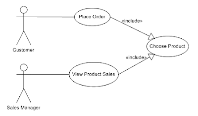
Figure1: Include


A customer can place an order and will always need to choose the product (s)he want to buy. A sales manager can review the sales of a product by choosing the product for which (s)he wants to see the sales figures.

Extend
The extend relationship allows an executing use case to call a certain extension use case under certain conditions.

The arrow of the relationship points from the extension use case (Correct Order) to the executing use case (Validate Order). This means that extension use case decides to impose itself on the executing use case.
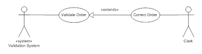
Figure2: Extend

If an error occurs in validating the order by the validation system, a user within the validation team can correct the order. The Correct Order extension use case is called under the condition that an error occurs in the validation of the order.

In both the include and extend relationship, the calling use case does not know how the included or extended use case works internally. It is called as a black box.

Generalisation
Generalisation allows (like for classes) to define an inheritance relationship between a general use case and more specific use cases. The specific use case inherits all features from the general use case.
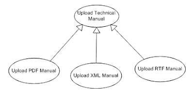
Figure3: Generalisation
Use Case Description
When describing the use case, the following items can be addressed. Mandatory items should not be omitted when describing a use case. As stated, this part is the heart of your functional requirement. Unfortunately UML does not describe any guidelines for this.

Mandatory Paragraphs

Name
Use a descriptive name. Your use case should always start with a verb!

Pre-conditions

These are conditions that must be met before the use case can start. If one of these conditions are not true, the use case cannot start.

The post-condition of a use case can also be the pre-condition of another use case. This indicates the logical flow between the execution of use cases.

Description
In the description, you can write a small narrative that describes the use case. Don’t forget to include the aim/goal of the use case, although sometimes this is too obvious to mention.

Remarks
Group here any remarks relating to the use case:
  • TO DO’s
  • Information about functionality omitted or reserved for a next phase
  • Open Questions
  • Technical decisions
Scenarios
This section describes the different scenarios in the use case. You define the different steps in the use case and the interaction between actor and the system.

We can distinguish 3 types of scenarios:

Primary scenario
This is the happy or normal flow that covers the normal sequence of steps if no error occurs.

Alternative scenarios
The alternative flows or scenarios, sometimes also called extension points, are alternatives of the primary scenario. For each step in the primary scenario, you should ask yourself the question: “Can this step have another outcome? Some of these extension points may also call extension use cases (see Extend). Sometimes you may continue after the alternative flow with a step of the primary scenario.

Exceptions
What happens in case of any failure/error during the primary scenario? They can be seen as a special kind of alternative scenario.

  • In complex scenarios, consider using an activity diagram to show all possible scenarios of a use case.
  • It is important is to find a way of indicating where in the normal flow alternative flows occur and where exceptions pop-up.
  • Remember that exceptions may also occur in alternative flows. Put these exceptions in the alternative flow, not in the exception flow, unless the same exception occurs in both the normal and exception flow.
Examples

Example 1
We write explicitly in the step of the primary scenario where the extension or exception occurs.

Primary Scenario
Step
Action
1
User enters search criteria
2
User presses “Search” button
3
System displays results of search
Extension 1
Extension 2
Exception 1

Extension 1
Step
Action
1
User presses “Cancel” button while searching
2
System issues message “Search cancelled”

Extension 2
Step
Action
1
System displays “No results found.”

Exception 1
Step
Action
1
System displays system error “System error: no access to query results.”
2
Post-Condition: search button is disabled.

You can also group all extension points and exceptions under one paragraph.

Normal Flow
Alternate Flow
·         Extension Point 1
·         Extension Point 2
 Exception Flow
·         Exception 1

Example 2
In this example we use a different notation: in the extension we use the number of the step in the primary scenario where the extension or exception happens.

Primary Scenario
Step
Action
1
User enters search criteria
2
User presses “Search” button
3
System displays results of search

Extension 1 at step 3
Step
Action
1
User presses “Cancel” button while searching
2
System issues message “Search cancelled”

Extension 2 at step 3
Step
Action
1
System displays “No results found.”

Exception 1 at step 3
Step
Action
1
System displays system error “System error: no access to query results.”
2
Post-Condition: search button is disabled.

Example 3
In this example we use the number of the step in the primary scenario in a slightly different way. The first number refers to the step of the primary scenario, the second number is a sequential number within the extensions or exception.

Primary Scenario
Step
Action
1
User enters search criteria
2
User presses “Search” button
3
System displays results of search

Extensions:
  • 3.1:
Step
Action
1
User presses “Cancel” button while searching
2
System issues message “Search cancelled”

  • 3.2:
Step
Action
1
System displays “No results found.”

Exceptions:
  • 3.1:
Step
Action
1
System displays system error “System error: no access to query results.”
2
Post-Condition: search button is disabled.

Post-conditions
The post-conditions describe the situation or state of the system/application when the normal flow of the use case ends. Placing them under a separate chapter in your use case increases their visibility, assuring these post-conditions are met when the normal flow of the use cases ends.


In some cases, you can also describe the post-conditions for each exception but you should place them in the Scenario part 


Optional paragraphs


Number

Numbering can be useful if you stick to a simple sequential number. If however you put some logic in your numbering (indication of functional group, main and sub use cases), you will end up in renumbering a lot of use cases, when new use cases pop-up, which inevitably will happen.

Assumptions
These are conditions the use case assumes to be true. The use case will never test them.
A typical example is that you need to be logged in and passed a security check before you can perform any use case within the application. To repeat this assumption for each use case is of course not needed.

Triggers
A use case is triggered by some event. The following events are typically used:
  • A time event fires of
  • A signal is received
  • A certain condition is met
  • A user initiates a certain action
  • A business event occurs
You can also use the first step in your scenario to define the event that initiates the use case. Up to you to decide which approach works the best.


Tuesday 7 February 2012

Writing high-quality Business Requirements

Some tips and guidelines to ensure your business requirements are of high-quality. This way your business requirements will form a solid and reliable basis for starting your project.

1. Preface

One of the key tasks for a business analyst is assisting the business in writing their business requirements (BR’s). This document wants to help them in writing high-quality business requirements, ensuring they do adhere to certain standards, so they can be used as the basis for starting the analysis of your project.

2. General Features

2.1 Categories
In general we can categorise requirements in two major categories:
  • Functional
  • Non-functional
    • Usability
    • Performance
    • Scalability
    • Security
    • Availability & Recovery
You can always split up your functional requirements in functional groups, depending on the modules or functional blocks in your project.
2.2 Style
You can choose for an informal style when defining user requirements or you can rely on the paradigm as used when writing user stories:
As a (role) I want (goal/desire/something) so that (benefit/reason).
2.3 Structured
Structuring BR’s will increase the consistency and make it easier to avoid duplicate BR’s.

Is a certain structure applied to the business requirements?
  • Grouped per category
  • Numbering the BR’s allows to easily refer to a given BR and track their progress
  • Use a descriptive name for each BR or underline the keywords in the description of the BR
  • Use hierarchy levels to start with high-level requirements that can be gradually detailed in lower-level requirements
2.4 Clear & Unambiguous
  • Requirements need to be clear and unambiguous so that you get what you actually need rather than what someone has assumed you need.
  • Is a glossary of terms available to ensure everybody understands the same when using a term? A glossary will help to:
    • Avoid using the same word in different meanings.
    • Avoid using different words having the same meaning
    • Avoid another misleading term is used
  • The text should not allow for different interpretations, so a good level of detail is needed.
  • It is critical that the BR’s are phrased in a consistent way, to avoid different interpretations if a requirement is worded many times and in different words.
  • A good mixture of text and graphs is always the best way of describing what the business expects from the new application.
  • No technical or architectural decisions should be put in the BR’s, only what the business expect from the system/application.
  • Clear and unambiguous requirements have the advantage that they can be easily tested after implementation.
2.5 Representative
  • Who created the BR’s is very important. For each BR you should document the person who requested the requirement. This way you know who to contact in case of any doubt or needed clarification.
  • Do they really represent the business (management as well as users that will use the new application)?
  • Do they represent all stakeholders (departments) that are involved in the business process?
2.6 Complete
  • Business users tend to describe the exceptions of their business process and sometimes forget to describe the normal flow, since for them this normal flow is so obvious.
  • Is for each business requirement indicated whether the BR is to be automated by the new application or that it is only a manual business procedure?
  • Ensure that the AS-IS and TO BE business process are described or include time to describes these before the analysis can start. Use BPMN or UML activity diagrams.
  • Are all involved departments/users involved?
2.7 Measurable
When deliverables of your project are being tested, you should be able to compare your business requirements with the deliverables you are testing. To ease this process, make sure your requirements are measurable. This is specifically important for non-functional requirements.
  • Include exact time or quantity units
  • Quantify your requirements
2.8 Prioritised and Phased
Users tend to say that everything they asked for needs to be available from day 1 in the new application. Define which requirements absolutely, positively have to be delivered in order for the system to be viable and your business case benefits to be realised. When changing priorities, ask yourself what the trade-off is if we prioritize this ahead of other requirements?

Following tasks should have a high priority for automation:
  • Focus on tasks that will increase the ROI
    • Costly tasks
    • Complex tasks
    • Labour-intensive tasks
  • Tasks that are required because of regulation/legislation by an external body
  • Tasks that are performed on a regular basis
  • Concentrate on the normal flow: exceptions should have a low priority

Use any kind of categorisation to prioritise the BR’s
  • For instance MOSCOW principle:
    • Must
    • Should
    • Could
    • Would
  • Phasing: split up the project in phases and assign a phase for each requirement
2.9 Tools
Ensure your business requirements can be created, viewed and adapted by anybody involved in gathering the business requirements. A collaborative web tool is the best way to ensure everybody is invited to comment and clarify the requirements and to track progress. This way the quality and accurateness of your requirements will increase, since more users are involved in the process. . If on the other hand you only have an even professional excel sheet, you should at least create a shared workbook in MS Excel to allow collaboration between all people involved.

These tools have to support version control, metadata fields (like prioritisation, creator, responsible, phase...), e-mail notification and other features common to issue and bug tracking tools. I worked with JIRA from http://www.atlassian.com/ and open source product TRAC from http://trac.edgewall.org/ and they are perfect for the job.